There are no items in your cart
Add More
Add More
| Item Details | Price | ||
|---|---|---|---|

Securing Your World, One Camera at a Time.
{{DATE}}
Ever wondered how CCTV systems actually work behind the scenes? This blog explores the key concepts and technologies behind CCTV systems, including how they work, different types of cameras, installation tips, and their benefits for security. Learn everything you need to know to choose the right surveillance system for your home or business.
Closed Circuit Television (CCTV) refers to a surveillance system where all components cameras, monitors, and recording devices—are directly connected in a closed loop, either through wired or wireless means. Unlike broadcast television, which sends signals over public airwaves, CCTV signals are restricted to a specific network, ensuring a more secure and private monitoring experience. CCTV is most commonly associated with security applications in locations such as retail stores, banks, and government buildings. At its most basic, a CCTV system consists of a camera connected to a monitor by coaxial cable, with power being supplied through the monitor itself.

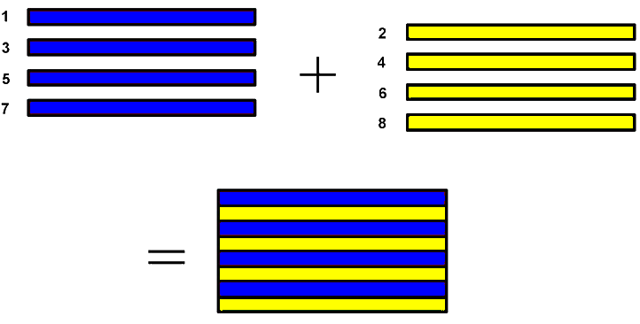
Analog television is the traditional method of transmitting television signals using continuous signals to represent both picture and sound. The system uses varying frequencies to transmit these signals, with the picture made up of a series of horizontal lines that are scanned onto the screen. A television picture is created by scanning these horizontal lines across the screen, from top to bottom. These lines are displayed in rapid succession, and when a series of still images is shown at a high enough rate, our brains perceive them as continuous motion. If the rate of images is increased to around 50 frames per second, the result is smooth, flicker-free video that gives the illusion of real-time motion.

The video resolution and clarity of the picture depend on the number of lines being scanned, with older systems offering lower resolution compared to modern digital systems. To reduce transmission bandwidth, analog television adopts interlaced scanning. In this method, one scan produces 312.5 horizontal lines from the top to the bottom of the picture, known as one field. The next scan starts at a precise position between the lines of the first scan, ensuring that the lines from the second field interlace between those of the first field, much like fingers interlocking. This technique allows a complete frame of video to be created by combining two fields, reducing the amount of bandwidth needed for transmission while still producing a full image.
The video resolution and clarity of the picture depend on the number of lines being scanned, with older systems offering lower resolution compared to modern digital systems. Since analog signals degrade over distance or with interference, the picture and sound quality could be affected, especially in areas with poor signal reception. Analog TV has largely been replaced by digital television, which offers better picture and sound quality, more efficient use of bandwidth, and advanced features like high-definition and interactive TV. However, analog television still has historical significance and some regions continue to use it for specific applications, such as CCTV or low-bandwidth broadcasts. Current video technologies implement progressive scanning. ie one scan produces the entire line from top to bottom. Interlaced scanning was a key innovation to make analog broadcasts more efficient, but with modern technology, progressive scanning (where every line is drawn sequentially in one pass) is more common for high-definition displays.
Raster & Aspect Ratio
Raster and aspect ratio are key concepts in video and image display systems. A raster refers to the grid of pixels that make up an image or video frame. It’s essentially the pattern of rows and columns of individual pixels that are displayed on the screen. In the context of television or video, the raster scan technique is used to display an image by scanning the lines from top to bottom, typically in a left-to-right pattern. This is how the image is "painted" on the screen. In analog TV, the raster is built up from a series of horizontal lines, with interlaced scanning breaking the frame into fields. The term "raster" is also used in digital systems like computer displays and video cameras, where images are stored and manipulated in a grid of pixels.
The aspect ratio refers to the proportional relationship between the width and height of an image or video frame. It is expressed as two numbers, typically written as width:height. For example, a common aspect ratio for HD video is 16:9, meaning the width is 16 units for every 9 units of height. Common aspect ratios include:
Relation Between Raster and Aspect Ratio
The raster defines how the image is displayed on the screen, and the aspect ratio determines the proportion of that image. For example, a 16:9 aspect ratio video will have a raster that consists of more pixels in the width than in the height to maintain that 16:9 proportion.

Basic CCTV System
A basic analog CCTV system consists of a camera and a monitor, both powered by the mains. A single coaxial cable carries both the video signal and the power to the camera, simplifying the wiring and installation process. This setup enables real-time video surveillance, making it suitable for small-scale security applications where minimal equipment is required.

System with Switcher
When multiple cameras are needed in a CCTV system, a video switcher is required. The switcher allows for the selection of any camera to be displayed on the screen, or it can be set to cycle through all cameras in sequence. The duration for which each camera is shown can typically be adjusted using a control knob or a screwdriver for finer settings.

System with Switcher & VHS Recorder
The next development in a CCTV system is the addition of a video recorder. With this setup, the pictures shown during playback will follow the same sequence as they were recorded, based on how the switcher was configured at the time of recording. For example, if the switcher was set to cycle through cameras in sequence, the same sequence of views will be displayed during playback. There is no control over what can be displayed during playback, as it simply mirrors the recorded sequence.

System with DVR
With the advent of digital technologies, digital video recording (DVR) was introduced. In this system, the video feed from an analog camera is digitized, compressed, and stored on a hard disk using the DVR. The DVR is equipped with a monitor output to view both live and recorded footage. Additionally, using software, the live feed and recorded video can be accessed remotely over a local computer network or the internet, offering increased flexibility and convenience for monitoring.

System with Hybrid DVR
As digital technologies advanced, digital cameras (IP cameras) became available, leading to the development of Hybrid DVRs. These Hybrid DVRs are capable of receiving both analog camera feeds and digital camera (IP camera) feeds. The video feed from an analog camera is digitized, compressed, and stored on a hard disk by the Hybrid DVR. Meanwhile, the IP camera feed, which is already digitized and compressed, is also received and stored by the Hybrid DVR. One significant advantage of IP cameras is the option to use Power over Ethernet (PoE). With PoE, the camera can be powered directly through the LAN cable, eliminating the need for separate power cabling. This allows both data and power to be transmitted over a single cable, simplifying installation and reducing the amount of wiring needed.

System with PoE IP Camera & NVR [Wired]
As digital technologies continued to advance, analog systems began to become obsolete. Network Video Recorders (NVRs) replaced Hybrid DVRs, with NVRs designed to receive video feeds from IP cameras. While the fundamental principles of video recording and storage remain the same, NVRs offer more features and greater flexibility thanks to digital control. The shift to NVRs allows for easier scalability, remote access, and enhanced video quality, as well as integration with other digital technologies, providing a more robust and future-proof surveillance solution.

System with PoE IP Camera & NVR [Wireless]
Further advancements in digital technologies introduced wireless capabilities to CCTV systems. With the availability of WiFi routers and switches, the need for extensive data cable wiring was significantly reduced. This wireless approach allowed cameras to connect to the system via WiFi, making installation easier and more flexible, especially in hard-to-reach or expansive areas. The ability to transmit both power and data wirelessly enhanced convenience while maintaining the quality and functionality of the surveillance system.

System with WiFi Camera & NVR
Later, WiFi-enabled wireless cameras became available, offering a major advantage: the need for separate wiring for data could be completely eliminated. This wireless setup allows for greater flexibility in installation, as cameras can be placed in locations where running cables would be difficult or costly. It also simplifies the overall system, reducing clutter and installation time.

Camera Housings

Box cameras are typically used in projects that demand greater control over lens settings, such as focus, zoom, and aperture. Their modular design allows for easy customization, making them ideal for applications where precise adjustments to image quality, field of view, and lighting conditions are required.

Fixed dome cameras feature a dome-shaped body with a centrally positioned lens, often integrated with infrared LEDs to provide illumination in low-light conditions. These cameras are commonly used in security applications due to their discreet design and ability to capture clear footage in various lighting environments.

Bullet cameras have a cylindrical shape, resembling bullets or cigars, and are typically equipped with a fixed focal length lens at the center. Many models also include infrared LEDs for enhanced visibility in low-light conditions, making them ideal for outdoor security applications. Their sleek design allows for easy mounting and targeted surveillance.

PTZ cameras, which stand for Pan, Tilt, and Zoom, offer remote control over the camera's movement and focal length. These cameras can pan horizontally, tilt vertically, and zoom in or out, allowing operators to adjust the field of view and focus remotely, typically via a computer or joystick. This makes them ideal for dynamic surveillance and tracking in real-time.
Camera Lens


A fixed lens camera offers a set viewing angle that cannot be zoomed or adjusted. These cameras are typically more affordable and are ideal for environments where the layout is unlikely to change, such as in a room of a house. They provide a stable, consistent field of view, making them a practical solution for straightforward surveillance needs..

A vari-focal or manual zoom lens allows for precise adjustment of the focus and viewing angle, enabling you to capture the specific area you wish to monitor. This flexibility ensures that the camera can be fine-tuned to achieve the ideal image. Additionally, it offers the advantage of being adjustable in the future if the layout of the area or your surveillance requirements change.
Effect of Lens Size & Distance

16mm
35mm

50mm

85mm

135mm

200mm
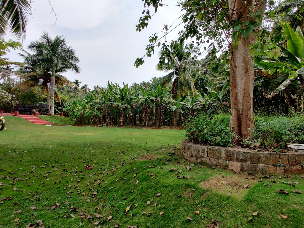
The size of the CCTV camera lens directly influences the viewing angle, determining how much of the scene the camera can capture. Additionally, the distance at which the camera is mounted from the subject affects the clarity and level of detail in the recorded image. A wider lens captures a larger area but with less detail, while a narrower lens offers more focused imagery but covers a smaller field of view.
Field of View

The field of view refers to the area that a CCTV camera can capture, also known as the viewing angle. It is influenced by factors such as the lens size, the CCD chip size, and the distance between the camera and the scene. A larger field of view allows the camera to cover more area, but objects appear smaller, whereas a smaller field of view provides a more focused image with greater detail on the target object.
Sensor Size

CCTV cameras are available with various chip sizes, including 1/4", 1/3", 1/2", and 2/3". The chip size plays a crucial role in determining the viewing angle—the smaller the chip, the narrower the field of view. Larger chips provide a wider angle, capturing more of the scene, while smaller chips focus on a more limited area with increased magnification.
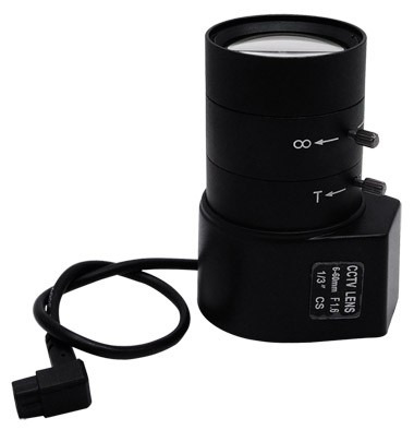
Lens Format


Early CCTV lenses were designed for 1-inch format tube cameras and featured a C-mount screw thread. A newer type of lens, known as the CS-mount, has emerged. The primary difference between C-mount and CS-mount lenses is the flange back length, which is the distance from the back flange of the lens to the sensor's surface. A lens designed for a larger format camera can be used on a smaller format camera, but not vice versa. While a C-mount lens can be used on a CS-mount camera with an adapter ring, a CS-mount lens cannot be used on a C-mount camera due to the difference in flange back length.
Depth of Field

Depth of field refers to the range within a picture where objects appear in focus. A large depth of field means that most or all of the scene is sharp and in focus, while a small depth of field results in only a small portion of the field of view being in focus, with the rest appearing blurred.
Iris

MANUAL IRIS
A manual iris allows the user to adjust the iris opening manually by rotating a knurled ring on the lens body. The range typically extends from the maximum aperture (wide open) to fully closed, enabling precise control over the amount of light entering the lens and the depth of field.

AUTO IRIS
An automatic iris uses advanced electronics and microscopic motors to adjust the iris ring automatically. The adjustment is based on the voltage of the video signal—when the voltage is lower, the iris opens wider to let in more light, and when the voltage increases, the iris closes to reduce light intake, maintaining the correct exposure for optimal image quality.
ICR


A camera filters out infrared (IR) light from sunlight using an Infrared Cut Removal (ICR) filter, which blocks unwanted IR light and ensures high-quality video with accurate colors. At night, the camera automatically moves the infrared filter out of the way to allow more light to reach the sensor, enhancing low-light performance. Cameras equipped with an ICR filter are known as True Day/Night cameras, as they can seamlessly transition between day and night conditions for optimal imaging.
Image Sensor

A lens focuses light onto the CCD or CMOS image sensor, where light and dark areas are captured by an array of tiny light-sensitive cells, converting them into electrical charges. A digital-to-analog converter then reads these charges, translating the varying levels of charge from individual cells into pixels of different colors. The low manufacturing cost of CMOS sensors makes them ideal for producing affordable consumer devices.
IR Illuminator

Infrared illuminators use IR LEDs that emit light in the infrared spectrum. These illuminators are commonly used in night vision cameras to provide visibility in low-light or complete darkness without visible light. In CCTV cameras, IR LEDs typically emit light at wavelengths ranging from 850nm to 940nm.
Power Over Ethernet (PoE)

IEEE developed the IEEE 802.3af standard to provide Power over Ethernet (PoE), delivering up to 15.4W over standard network cables. This technology eliminates the need for a separate power supply for network devices, such as IP cameras and IP phones, simplifying installation and reducing costs. In 2009, the standard was updated to IEEE 802.3at, also known as PoE+, which increased the power output to 25.5W. This allows more power-hungry devices to be powered over the same network cable.
Key Components
A power injector is a device that sits between a regular network switch and a device to be powered, such as an IP camera. It injects power into the Ethernet cable without requiring a PoE-enabled switch. This makes it easier to upgrade existing network infrastructure to support PoE devices. By using PoE and power injectors, installations become more cost-effective, especially for remote or hard-to-reach devices like IP cameras, where running separate power cables would be expensive or difficult.
PTZ Camera

A PTZ (Pan-Tilt-Zoom) dome camera refers to a type of surveillance camera that is mounted on a movable platform, which is known as a pan-tilt unit. This unit allows the camera to rotate horizontally (pan) and vertically (tilt), providing flexible and dynamic coverage of an area. The term "zoom" refers to the camera's ability to adjust its focal length, enabling it to focus on distant objects without physically moving the camera. The combination of pan, tilt, and zoom functions makes PTZ dome cameras highly effective for monitoring large or complex areas in real-time, especially in security and surveillance applications.
To control a PTZ dome camera, you can run cables in parallel with the coaxial cables and utilize an RS-485 interface, which supports long-distance communication for controlling the camera. A standard protocol like Pelco-P or Pelco-D can be used over the RS-485 interface to send control commands for pan, tilt, zoom, and other camera functions. Pelco-P and Pelco-D are communication protocols developed by Pelco, a well-known camera manufacturer. These protocols are widely adopted in the industry for PTZ camera control, and both protocols provide compatibility across different brands of PTZ cameras, which may use varying communication standards. When integrating devices from different manufacturers, it's crucial to ensure that both the analog PTZ camera and the joystick (or DVR) support the same protocol to ensure proper command transmission. Choosing the right protocol (Pelco-P or Pelco-D) is key to maintaining compatibility between different equipment, as these protocols define the format and structure of the control signals. In environments with mixed equipment, using a common protocol like Pelco-P or Pelco-D ensures that the PTZ camera can be operated reliably, regardless of the brand.
WDR Camera


When a CCTV camera is pointed at an entrance, door, or window, the image can often suffer from uneven lighting, with some areas overexposed (too bright) and others underexposed (too dark). This is typically caused by high contrast lighting conditions, such as sunlight coming through a window while the interior remains dimly lit. To solve this issue, Wide Dynamic Range (WDR) is employed, which helps balance these differing light levels across the scene. WDR works by compensating for areas with excessive brightness and those that are too dark, resulting in a more evenly exposed image.
Here’s how the camera’s shutter operates when using the WDR feature:
Data Transmission
In CCTV systems, various methods of data transmission are used to send video and control signals from cameras to recording devices, monitors, and control centers. Each transmission method has its place in a CCTV system, depending on factors like distance, budget, system scale, and the environment in which the cameras are installed. A summary is given here.
| Method | Typical Use | Advantages | Limitations |
| Coaxial Cable | Analog CCTV systems, HD over coax | Cost-effective, easy to install | Limited distance, no power over cable |
| Ethernet Cable | IP CCTV systems | Supports data and power, scalable, long distance | Higher cost, requires network infrastructure |
| Optical Fibre |
Large-scale, high-bandwidth systems | Very long-distance, high-speed, interference-free | Expensive, requires specialized equipment |
| Radio |
Wireless CCTV systems, remote locations | Flexible installation, no cabling needed | Limited range, potential interference |
Resolution


Resolution refers to the ability to capture fine details in an image. In analog CCTV cameras, resolution is often measured in TV Lines (TVL) or by standard definitions like 480, 540, 600, 1000, 720p, 1080p, HD, and Full HD. TV Lines represent the number of vertical lines displayed on a monitor—the higher the TVL, the higher the resolution and more detail the camera can capture. For analog cameras, the image is converted to a digital format via a DVR (Digital Video Recorder). On the other hand, IP CCTV cameras capture and transmit video directly in digital format. Terms such as CIF, 2CIF, 4CIF, VGA, SVGA, XVGA, HD, Full HD, Mega Pixel, and 4K are used to describe digital resolution in CCTV systems, with higher values corresponding to better image clarity and detail.

Bit Rate

Bit rate determines the quality of video by balancing factors like frames per second (FPS), resolution, and image compression. It measures the amount of data (in bits) transferred from one point to another over a specified period of time. "bps" stands for "bits per second," a unit used to express bit rate. A higher bit rate generally means better video quality, as more data is used to represent each frame. Conversely, decreasing the bit rate leads to a reduction in video quality, as less data is allocated per frame. Factors such as resolution, frame rate, and compression settings all impact the bit rate, as shown in the figure. These elements must be balanced to optimize both video quality and the required bandwidth.
DVR

A DVR (Digital Video Recorder) is a device used in video surveillance systems to record, store, and manage video footage from CCTV cameras. Unlike older analog systems that used VCRs (Video Cassette Recorders), a DVR records video in a digital format, making it easier to store, retrieve, and manage video data. Here are some key features of a DVR:
Compression

A DVR (Digital Video Recorder) or NVR (Network Video Recorder) utilizes advanced compression algorithms such as H.264+, H.265, and H.265+ to efficiently reduce video file sizes while maintaining high image quality. This compression helps save storage space and reduces bandwidth usage when transmitting video over a network. The process of compression and decompression is handled by CODECs (Compressor-Decompressor).
Why Compression is Necessary?
A single frame of PAL monochrome video requires approximately 450KB of storage, while a color frame requires about 650KB in its uncompressed form. For continuous video recording, this results in enormous storage requirements:
How CCTV CODECs Work?
A CCTV CODEC reduces video file size by identifying and removing redundant data. The term CODEC can be broken down into:
MJPEG, MPEG-4/H264

MJPEG (Motion JPEG) is a video compression technique where each video frame is compressed as a separate JPEG image and transmitted in rapid succession. Essentially, it treats each frame as a still image, resulting in a sequence of individual, complete images. This gives the illusion of continuous motion when viewed at a sufficient frame rate. While MJPEG is simple and easy to implement, it tends to be inefficient in terms of storage and bandwidth because each frame is fully compressed independently. For example, a typical 450KB uncompressed frame can be reduced to 30KB using MJPEG compression.
MJPEG Limitations:
How MPEG/H.264 Works?
Motion Detection

A Video Motion Detection (VMD) system is designed to assist CCTV operators by automating the monitoring process. Instead of constantly observing live video feeds, which can be tedious and ineffective when there is little or no motion, the VMD system continuously monitors all cameras and only triggers an alarm when suspicious activity or motion is detected.

In Video Motion Detection (VMD), a cell is the smallest unit of the video frame that is analyzed for changes in brightness. Each cell is essentially a block of pixels, and its brightness is monitored to detect any variations. When there is movement or a change in the scene, the cell will register a difference in brightness. A zone is a group of cells that are defined as a specific active area within the frame. In a surveillance scenario, certain parts of the scene (like near a door) may be set as an active zone, while other areas (like a background or hallway) may be considered inactive zones. Active Zones are the areas where movement will trigger an alarm (e.g., the door area). Whereas Inactive Zones are the areas where movement or changes will be ignored (e.g., a background with little to no movement). The system only monitors the active zones, reducing unnecessary alerts from areas with little to no interest. Cell Count refers to the number of cells in the active zone that have undergone a simultaneous change in brightness (due to motion). For an alarm to be triggered, a threshold value is set. This is the minimum number of cells that must change to generate an alarm. For example, if more than ‘x’ cells in the defined zone change brightness simultaneously (indicating movement), the system will trigger an alert. This threshold helps reduce false alarms caused by minor, insignificant changes in the environment (such as changes in lighting).
How It Works:
The system continuously monitors the video feed and divides the image into cells. Each cell’s brightness is analyzed for changes, and a zone is created for areas of interest (e.g., a doorway). The Cell Count is tracked for any changes in the active zone. If the number of changed cells exceeds the preset threshold, the system considers it as suspicious activity and triggers an alarm. In a situation where the active zone is set around a door, only changes in that specific area will be analyzed. If, for example, a person walks through the doorway, multiple cells in the active zone will change simultaneously. If the number of changed cells exceeds the threshold (e.g., 10 cells changing brightness), an alarm is triggered. If only a few cells change, it might be dismissed as insignificant (e.g., a shadow passing). By using the Cell Count and defining Zones, the VMD system can accurately detect movement in specific areas of interest while filtering out irrelevant changes, reducing operator workload and improving overall system efficiency.
Storage Calculation

Bandwidth Measurement

To ensure the system operates smoothly without crashes, bandwidth usage at specific points in the network must be carefully monitored. The setup typically involves an IP camera connected to a router, which is then linked to a laptop and an NVR (Network Video Recorder). You can measure the bandwidth usage by using the Windows Task Manager to monitor the network performance on the laptop. From there, adjust the bitrate or make network corrections to meet the required bandwidth needs. By optimizing the bitrate and regulating traffic, you can ensure that the system performs efficiently without exceeding the available network capacity.
Screen Splitter Display

A screen splitter is a device or feature that allows multiple camera feeds to be displayed on a single screen, enabling efficient monitoring of several areas at once. These splitters combine multiple camera outputs into a single screen, offering a consolidated view of various camera views. A Quad Screen Splitter (2x2) splitter allows the display of four camera feeds on a single screen, arranged in a 2x2 grid. Each section of the screen shows a live feed from one camera, allowing the operator to monitor four areas at once. Like wise a 3x3 Screen Splitter enables the display of nine camera feeds on one screen, whereas a 4x4 splitter displays sixteen camera feeds on one screen. By using screen splitters, CCTV operators can monitor multiple camera feeds at once, improving efficiency and reducing the need for constant switching between different camera views.
Software

The DVR/NVR/IP CCTV camera systems have the capability to send video feeds to remote devices like laptops, desktop computers, tablets, or mobile phones. This remote access is typically facilitated through a network connection, whether it's over a LAN (Local Area Network), WiFi, or the Internet. This allows users to monitor live video or recorded footage from virtually anywhere.
When within the same local network (LAN or WiFi), the DVR, NVR, or IP camera can transmit video directly to devices connected to the same network. This is the simplest form of remote viewing and requires no external internet connection. For example, monitoring the CCTV system within a building or office environment.
For remote viewing outside of the local network, video can be accessed over the internet via Dynamic DNS (DyDNS), a static IP address, or cloud services. DyDNS is a service that allows users to connect to a device (like a DVR, NVR, or IP camera) using a domain name, even if the device’s IP address changes periodically (as is common with residential ISPs). The Dynamic DNS service automatically updates the domain name with the new IP address, making it easier for users to connect to their CCTV system remotely, without needing to track the IP address manually. This is ideal for users with dynamic IP addresses from their internet service provider (ISP).
A Static IP address is a fixed, unchanging IP address assigned to the DVR, NVR, or IP camera. With a static IP, users can connect to their CCTV system at any time using the same IP address. It is suitable for businesses or installations where reliable, constant remote access is needed. Static IP addresses are typically more expensive and require additional setup through the ISP.
Many modern CCTV systems offer cloud-based solutions, where the video feeds are stored and accessed through cloud platforms. These services typically include remote viewing via mobile apps or web interfaces, allowing users to easily monitor their cameras from anywhere with an internet connection. This method is very popular for residential users or small businesses who prefer an easy-to-use, hassle-free remote access solution without worrying about network configurations or static IP addresses.
To view CCTV footage on mobile devices (smartphones or tablets), users typically need to install specific apps provided by the camera or NVR/DVR manufacturer. These apps are available on app stores (e.g., Google Play or Apple App Store) and allow users to connect to their CCTV system via LAN, WiFi, or Internet. The app enables functions such as live streaming, video playback, and event alerts while on the go.
These methods provide flexibility and convenience, allowing users to monitor their CCTV systems remotely from anywhere with internet access, whether at home, at work, or while traveling.
Universal Streaming and Control Protocols

Universal Streaming and Control Protocols are standardized communication protocols that enable the streaming of video and the control of devices (such as CCTV cameras, DVRs, NVRs, or IP cameras) across various networked environments. These protocols allow for seamless integration, remote monitoring, and control, regardless of the device's manufacturer or the system's complexity.
RTSP (Real-Time Streaming Protocol) is one such protocol. It is a network protocol designed for real-time streaming of video and audio. It is commonly used to control the playback of multimedia content and also supports control commands such as pause, play, seek, and stop. Its often used in IP surveillance systems for streaming video from IP Cameras to networked video recorders (NVRs) and video management software (VMS) over local or wide-area networks.
ONVIF (Open Network Video Interface Forum) is a globally used protocol for video management and control. ONVIF is a global standard for IP-based physical security products (e.g., cameras, recorders, access control systems). It ensures interoperability between devices from different manufacturers. It provides standardized protocols for video streaming, device discovery, and device control. It supports features such as PTZ control, motion detection, video streaming, and audio streaming. It is designed to be device-agnostic, so cameras and NVRs from different brands can communicate seamlessly. This is very commonly used in enterprise-level surveillance systems.
HTTP/HTTPS (Hypertext Transfer Protocol) is another protocol method used. HTTP is the foundation of data communication on the World Wide Web, and HTTPS is its secure version. Many IP cameras and NVRs use HTTP/HTTPS for web-based control and streaming.
These protocols enable different types of video surveillance and monitoring, ensuring flexibility and compatibility across various devices and networks, making it easier to build scalable, interoperable CCTV systems.
CCTV systems have evolved significantly, transitioning from basic analog setups with coaxial cables to advanced digital solutions. Initially, analog cameras transmitted video signals via coaxial cables to monitors, but with the advent of digital technologies, DVRs replaced analog recorders, offering digital storage and remote access. As IP cameras emerged, Hybrid DVRs were introduced to handle both analog and digital feeds, later giving way to Network Video Recorders (NVRs) that provided greater flexibility and features. The addition of Power over Ethernet (PoE) enabled cameras to receive both power and data through a single cable, reducing wiring complexity. Further advancements introduced wireless (WiFi-enabled) cameras, eliminating the need for separate data cables and offering even more installation flexibility. Today, CCTV systems are more efficient, scalable, and accessible, providing enhanced security for both homes and businesses.
We discussed various hardware elements of CCTV systems, including the different types of cameras such as box, dome, bullet, PTZ, and fixed lens cameras, each with specific features suited for various surveillance needs. We also covered lens types like fixed, vari-focal, and manual zoom lenses, and how factors like lens and chip size influence the field of view and resolution. The conversation included how resolution impacts image quality in both analog (TVL) and digital formats (720p, 1080p, HD, Full HD, etc.) Additionally, we explored how bitrate affects video quality, with factors like FPS, resolution, and compression playing a role, and the importance of measuring and regulating bandwidth usage through tools like Windows Task Manager to ensure the system operates efficiently without exceeding network capacity.
We also explored various aspects of modern CCTV systems, including the use of PTZ dome cameras for flexible surveillance with protocols like Pelco P and Pelco D, which enable remote control. We also discussed the importance of Wide Dynamic Range (WDR) for balancing lighting in challenging environments and the role of video compression technologies such as H.264 and H.265 in reducing storage needs while preserving video quality. Video Motion Detection (VMD) systems, which use cells and zones to detect motion, help optimize monitoring by triggering alarms for suspicious activity. Power Over Ethernet (PoE) simplifies installations by combining data and power over a single Ethernet cable. Additionally, we explored different video transmission methods, including coaxial, Ethernet, and optical fiber cables, along with the use of screen splitters to display multiple camera feeds. Finally, we highlighted the convenience of remote viewing via LAN/WiFi/Internet, facilitated by cloud services and apps for mobile devices, contributing to more efficient and scalable surveillance solutions.

{{AUTHOR}}
Our vision is to create a platform where anyone could upskill as well as build their knowledge on hardware & firmware development through industry relevant courses in electronics, programming & mathematics at affordable prices.
 Launch your Graphy